Friday, May 18, 2012

Improved stl-file

I have made the stl 'watertight'. I make my stl-files in Rhino. Rhino gives this tip on stl:

1 Join the mesh objects.
Conceptually, this command gets all the triangles into one bag, but it doesn't glue the edges together. (The situation is similar to having surfaces that all fit together but have not been joined into a solid.) 
2) Weld the new mesh object.
3) At the Angle tolerance prompt type 180.
An angle tolerance of 180 tells the Weld command to glue adjacent triangle points together no matter what. 
4) UnifyMeshNormals.
This changes all the triangles so they are oriented the same way, that is, if two triangles share an edge, then they have the same idea of up.

It could be that using a watertight stl improves the mesh quality but I found some holes at the bottom... (You have to click on the picture to enlarge or look at the slice) Rhino reported it changed the normals of a quite lot of cells...

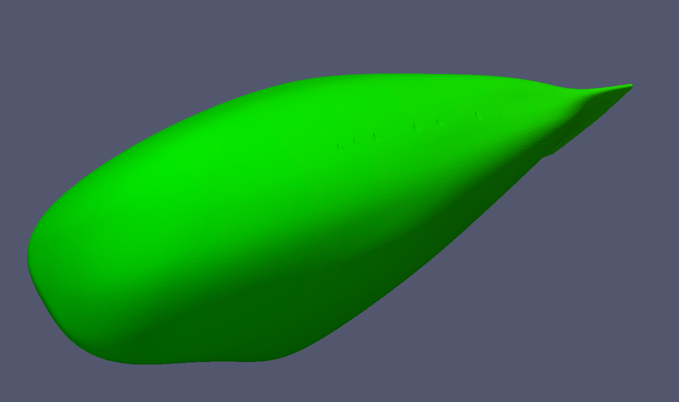
Looks like a perfect mesh: no bumps or holes
The trailing edge is pretty sharp

Oops holes !
A slice through the bumpy zone

Experiment with snappyHexMesh

I have created a simple knotted sphere in Rhino. Snappy generates a perfect mesh now... I used the same snappyHexMeshDict as in previous meshing of my guppy.


edge refinement at the cut

The red line is the edge for the Explicit feature edge refinement
Later I have done layer addition: 10 layers absolute thickness, expansion ratio 1.2. The result is not perfect to my lay eye.

The layer addition is not perfect


Thursday, May 17, 2012

meshing with featureEdgeMesh

With the snappyHexMesh utility a mesh can be constructed from a stl-file. I have extracted edges from the same stl-file with the surfaceFeatureExtract utility. These edges are used in the 'Explicit feature edge refinement' phase of the snappyHexMesh utility. This improves the quality of the edges of the mesh. But how can it be that the mesh is smaller than the edges extracted from the original stl-file ?

Another problem are the irregularities on the body. What went wrong? Is it the quality of my stl-file?

The mesh is smaller than the original stl-file !


 Two irregularities are visible.


a slice through the bumps

Original file (iges exported from proE)
holes on the top...
Yes they really are there
no mesh leaked inside


Tuesday, May 15, 2012

Thickness of the boundary layer

See this wiki page

For laminar boundary layers over a flat plate, the Blasius solution gives:
 \delta \approx 4.91 \sqrt{ {\nu x}\over u_0}
 \delta \approx 4.91x/ \sqrt{R e_x}
For turbulent boundary layers over a flat plate, the boundary layer thickness is given by:
 \delta \approx 0.382x/ {R e_x}^{1/5}
where
 R e_x = \rho u_0 x/\mu
 the overall thickness (or height) of the boundary layer
\nu is the kinematic viscosity
x is the distance downstream from the start of the boundary layer
Re_x is the Reynolds Number
\rho is the density
u_0 is the freestream velocity
\mu is the dynamic viscosit
My parameters
u_0~10m/s, \nu~1.5e-6, x~2 m.

 R e_x = \rho u_0 x/\mu
with \rho/\mu = \nu
Re_x=u_0 * x / \nu=1.33e7

\deltalaminar=0.0027 m = 2.7 mm
\deltaturbulent=0.0287 m =28.7 mm

In my mesh I will make 30 layers on the body with a total thickness of 30 mm. The thinnest layer will be 0.3 mm thick. With an expansionratio of 1.15 I will need 33 layers for 30 mm


Sunday, April 29, 2012

Lutz body


The Lutz body (regime I). DxL 0.62x2.84 [m], Volume 0.5 m3

I have done a CFD evaluation on the Lutz body. Free airspeed 10 m/s. Very low drag. (pressure 0.38 N viscous 1N). Re_v 5e5, Cdv 0.037. To good to be true. I have put the body near to a floor. For a comparison with the Lutz paper I should not have done that... Can anyone comment on this very low drag figure?

On the body p/rho [(m/s)^2], field velocity [m/s]
Why is it not possible to plot streamlines near to the body?

On the body p/rho [(m/s)^2], field velocity [m/s]

Optimized body

I found this recent paper on optimization of a streamlined body:

DRAG REDUCTION AND SHAPE OPTIMIZATION OF AIRSHIP BODIES, Th. Lutz and S. Wagner, Institute for Aerodynamics and Gas Dynamics, University of Stuttgart, Germany, 1997, American Institute of Aeronautics and Astronautics, Inc. (You can find it on the web).

In this paper bodies with minimal drag are presented for five design regimes that are defined with the volumetric Reynolds Number. Volumetric Reynolds Number and drag coefficient are defined as:


U_inf  undisturbed free stream velocity
V       body volume
v        kinematic viscosity
rho     air density

The figures below are from the paper. For my velomobile Re_v would be 10*1^(1/3)/15e-6 = 7e5. At Re_v = 1e6 the body of figure 7 has a Cd_v of ~0.075. In my CFD of the Quattro I have found a total drag of ~3 N at 10 m/s. When I assume the volume of the Quattro to be 0.7 m3 the Cdv is: 3/(1.2/2*10^2*0.7^(2/3)) = 0.06.  I will try to evaluate the body of figure 7 with OpenFOAM.


Saturday, April 28, 2012

Guppy 2


I have made the body longer and the S-tail less wavy. Forces : pressure drag 0.9 N viscous drag 1.2 N.
velocity [m/s]

velocity [m/s]
p/rho [(m/s)^2]
p/rho [(m/s)^2]
flow in the clearance between bottom and floor

Streamlines, velocity, pressure


I think I have to round the bottom edge of the nose. Why do the streamlines disappear? Is that turbulence?  Aerodynamic experts are invited to comment!