Sunday, April 29, 2012

Lutz body


The Lutz body (regime I). DxL 0.62x2.84 [m], Volume 0.5 m3

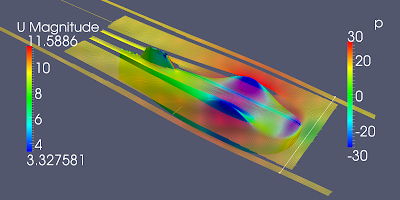
I have done a CFD evaluation on the Lutz body. Free airspeed 10 m/s. Very low drag. (pressure 0.38 N viscous 1N). Re_v 5e5, Cdv 0.037. To good to be true. I have put the body near to a floor. For a comparison with the Lutz paper I should not have done that... Can anyone comment on this very low drag figure?

On the body p/rho [(m/s)^2], field velocity [m/s]
Why is it not possible to plot streamlines near to the body?

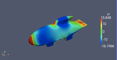
On the body p/rho [(m/s)^2], field velocity [m/s]

Optimized body

I found this recent paper on optimization of a streamlined body:

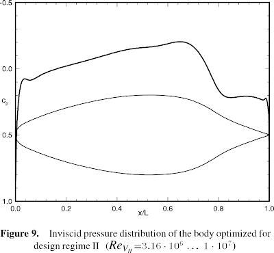
DRAG REDUCTION AND SHAPE OPTIMIZATION OF AIRSHIP BODIES, Th. Lutz and S. Wagner, Institute for Aerodynamics and Gas Dynamics, University of Stuttgart, Germany, 1997, American Institute of Aeronautics and Astronautics, Inc. (You can find it on the web).

In this paper bodies with minimal drag are presented for five design regimes that are defined with the volumetric Reynolds Number. Volumetric Reynolds Number and drag coefficient are defined as:


U_inf  undisturbed free stream velocity
V       body volume
v        kinematic viscosity
rho     air density

The figures below are from the paper. For my velomobile Re_v would be 10*1^(1/3)/15e-6 = 7e5. At Re_v = 1e6 the body of figure 7 has a Cd_v of ~0.075. In my CFD of the Quattro I have found a total drag of ~3 N at 10 m/s. When I assume the volume of the Quattro to be 0.7 m3 the Cdv is: 3/(1.2/2*10^2*0.7^(2/3)) = 0.06.  I will try to evaluate the body of figure 7 with OpenFOAM.


Saturday, April 28, 2012

Guppy 2


I have made the body longer and the S-tail less wavy. Forces : pressure drag 0.9 N viscous drag 1.2 N.
velocity [m/s]

velocity [m/s]
p/rho [(m/s)^2]
p/rho [(m/s)^2]
flow in the clearance between bottom and floor

Streamlines, velocity, pressure


I think I have to round the bottom edge of the nose. Why do the streamlines disappear? Is that turbulence?  Aerodynamic experts are invited to comment!

Guppy

I have sketched a new shape with a fish like tail. I think I have over done it a bit. I did a CFD at 10m/s. It looks like the flow separates at ~ 0.6 from the front. Forces : pressure drag 1.4 N viscous drag 1.1 N. My guppy is not a realistic velomobile: the head space is missing, the shoulder space and ground clearance are much to small.

I very happy that I can sketch a new shape and evaluate the aerodynamics in one day only... (Although I should be very modest about the quality of my judgements)

The fish tail with S-curve 
Shorter


Compared with the Quattro (Quattro is a design of Miles Kingsbury)

p/rho [m^2/s^2]
Air velocity

Tuesday, April 24, 2012

Layer addition

In the rounded corners snappy did not add layers.
The layer addition process succeeded not at the wheel fairings

Sunday, April 22, 2012

Problem with servers in ParaFoam

Every time I start Paraview from the terminal with the paraFoam command it tries to connect to servers that are non existent. This may take minutes! I tried to find the server.pvsc files that are described in the Paraview wiki but can't find them. I use the compiled OpenFoam 1.7 version of the ETH Zurich (http://www.ifd.mavt.ethz.ch/educatio...foam/of-macosx)

I found a temporary solution: (Thank you Bruno). Instead of starting via paraFoam, start paraView. When I use the recent file option ParaView does not try to connect to non existing servers.

Yes I am still a CFD dummie

There is still a lot to learn. This is what a professional thinks about my job: 

Here's some tips, but please consider that everything depends upon where you want to get with this job. If you want to get numbers as close as possible to the real ones (let's say CFD can do that…) than you need something "more", while if this is something you did to practice with openFoam, then it's already more than ok! So, I'll give you some advises as if you were selling this simulation to a company. Otherwise you can even ignore them.

1. Domain:
Your car is 3m long. Your domain is 2 car lengths in front of the car, 5 in its back, 5 lengths wide and 3 lengths tall. Now, the width is slightly ok, you could possibly have it from Y-10 to Y+10 anyway. You should definitely increase it along the X direction. I'd say bring it from X-12 to X+30. Also increase it's height up to Z+10.

2. Volume Mesh
You have 4 refinement regions around your car. Probably 3 would be ok as well. You should extend two of them (the coarser ones) down to the end of the domain. Also increase the width of these two. The coarsest of all should be at least twice as wide.


3. Surface Mesh
Your surface mesh is pretty much ok, but you should have smaller cells on the fairings, otherwise you may end up with a separation in that regions and that would increase your drag. Also, the trailing edge of the fairings is pretty bad, especially for the wheel's fairings (see image attached). You have two ways to improve those: a. separate them into a different stl file (or stl region) and give them a finer mesh level within the sHM dictionary; b. use featureEdges (probably the best solution in this case). For a case like this you should probably end up with, at least, 20M cells (you have 5M cells now). You probably want to run your case in parallel splitting your domain among the number of processors you have available.

4. Iterations
500 iterations is definitely too low. You'll probably need 2000 of them to get to a good convergency.

5. Forces
You should average your forces among the last 500 iterations.

6. Log
Always send the output of every command to a log file. This is useful for a large number of reason. One of them is that if you have your solver log (in this case the simpleFoam log) you can run foamLog and make sure you case actually got to converged results.

7. Layers
You have 10 layers on you car… that's really a lot! I would stick to 3 layers maximum and, since the lower face of the domain is a wall, I would have 2 layers on it as well.

8. Wheels
Your car is missing the wheels, which are a quite important component for the aerodynamics. You could use a rotating reference frame on them and use MRFSimpleFoam as a solver to solve the car with the wheels as if they were rotating!

9. Plots
I saw the pictures on your blog. Sorry, but you cannot get anywhere with those… You should use a smaller scale and possibly change the color schema to something more "traditional", for instance look at the image attached.

10. Movies
I made a small movie. You can find it in the folder in dropBox. I think a movie is something quite nice to show and it's more impressive to people than pictures.

Thursday, April 19, 2012

Second try

I have scaled the spats to meters and remeshed it.

A longitudinal clip through the new mesh.


Detail of the mesh. Does this look good?
I had to adjust some geometry data in the snappyHexMeshDict too.

Every time I start Paraview from the terminal it tries to connect to servers that are non existent. This may take minutes!
This is what I get 4 times every time I start Paraview
I tried to find the default_servers.pvsc and server.pvsc files that are described in the Paraview wiki but can't find them. Who tackled this problem and is willing to help? I use the compiled OpenFoam 1.7 version of the ETH Zurich.

Below you see the results after 500 steps. What I find very hard to believe is that now I have scaled te body with 1/1000 the pressure distribution is almost the same. In the first simulation the body was in mm. and the pressure range -225 to 50 now the body is is meters and the pressure range -185 to 50.

These are the forces on the body:
# Time    forces(pressure, viscous)
506    (((1.6243 0.398176 -18.9121) (1.52785 -0.00296421 0.00193884))
The total drag would be something like 1.6+1.5 =3.1 N (vehicle speed 10m/s)
There is a large downwards force of -19 N!

Let's compare this with the experience of Miles kingsbury: His estimates for the Quattro:
Cd_A of 0.12, A 0.6 m^2. At 10m/s the drag would be 4.32 N ( F = rho/2*Cd*A*v^2 ).


Pressure p/rho [m^2s^-2]

Tuesday, April 17, 2012

First run done

This morning the first calculation was ready. I used the simpleFoam solver with a k-omega model.
streamlines and pressure on the spats
Here an expert (not me) can evaluate the convergence
Time = 403
smoothSolver:  Solving for Ux, Initial residual = 5.14663e-05, Final residual = 4.49128e-06, No Iterations 3
smoothSolver:  Solving for Uy, Initial residual = 0.000128727, Final residual = 1.06587e-05, No Iterations 3
smoothSolver:  Solving for Uz, Initial residual = 7.15543e-05, Final residual = 5.27129e-06, No Iterations 3
GAMG:  Solving for p, Initial residual = 0.000129478, Final residual = 6.41391e-06, No Iterations 2
time step continuity errors : sum local = 3.84464e-10, global = 1.62637e-11, cumulative = 7.5432e-07
smoothSolver:  Solving for omega, Initial residual = 5.26723e-07, Final residual = 3.78036e-08, No Iterations 3
smoothSolver:  Solving for k, Initial residual = 3.84651e-06, Final residual = 2.74064e-07, No Iterations 3
ExecutionTime = 10837.4 s  ClockTime = 11064 s


I learned that CFD people usually use a reduced pressure: p/rho. This originates from Bernoulli: the dynamic pressure p = rho/2*v^2. p/rho equals 1/2*v^2. I set the air density rho to 1.2 [kgm^-3]. This would mean that the pressure range is -226*1.2 to 50*1.2, -271 to 60 [Pa]. Atmospheric pressure is 1e5 [Pa]. In the CFD only relative pressures are calculated. (I found a declaration of pressure in a file initialConditions somewhere, it was set to 0). The lowest pressure is 1e5 -271 [Pa], the highest 1e5 +60 Pa. The pressure change is very small relative to the atmospheric pressure. ~200/1e5=2e-3=0.002 (0.2 %). Please correct me if I'm wrong.
 
Pressure on the body. p/rho [m^2/s^2]

Something went wrong. Is is the mesh or is it paraview ?
 
The bottom view shows low pressure spots. p/rho [m^2s^-2]
Air speed [m/s] in a slice of the air 60 mm above the ground. (vehicle speed is 10m/s)
The pressure distribution in mid plane p/rho [m^2s^-2]

The air is moving through the narrow space between wheel 'pants' bottom and road. In this narrow space the air velocity rises and pressure falls.

Now I would like to find out:
  1. are my statements about the pressure above correct?
  2. is there something wrong with the mesh?
  3. how do I check the quality of the simulation using the lines on Final residual?
  4. how do I calculate the forces on the body due to kinematic pressure and viscosity (skin friction)?
  5. in the boundary layer what is the type of flow: laminar or turbulent? 
  6. I found out that the mesh is in [mm]. Both in the blockMeshDict and the snappyHexMeshDict the geometry is in mm. But shouldn't it be in [meter]. I know I can use to keyword convertToMeter in  blockMeshDict but what about the snappyHexMeshDict?
I hope someone is willing to help me on this.

Sunday, April 15, 2012

Spats meshed

With help of Ries Bouwman I managed to mesh the body of the Quattro. Next step will be to define boundary constraints and then run the calculation.
The mesh